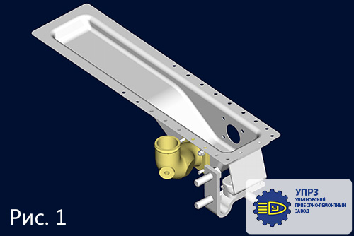
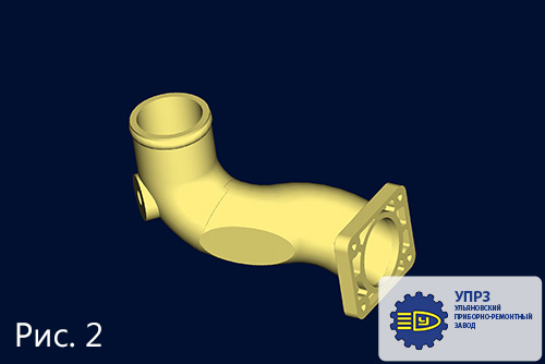
The part pipe joint is to apply in the item «Trac radiator» (fig.1). Initially this pipe joint was made by casting into the ground from aluminum alloy (fig.2).
The radiator manufacturer set a task with the transition from aluminum alloy to plastic to improve technical and economic indicators. The material Armlen ППСВ15-1 fully compare for this aim. We concerned several variants of pipe joint’s construction, including welded option.
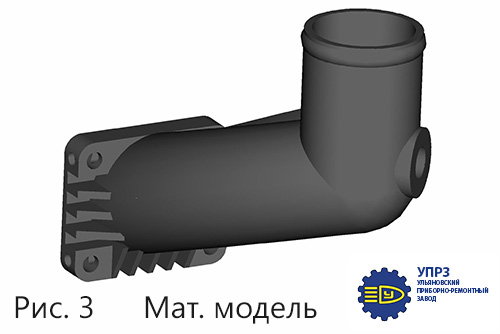
Finally, we came to the option shown in figs. 3 and 4, suitable in design (the pipe joint should be installed on the radiator and fit into the engine room) and manufacturing technology (casting on injection molding machine). The specialty of the pipe joint is in geometry, specifically one of its elements is difficult of accomplishment radial section at an angle 20 degrees, and also it is necessary simultaneously make a threaded hole.
The holes for installation of the pipe joint in the mold couldn’t be realized, therefore they are performed out of the mold by mechanical operation.
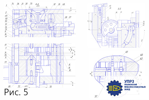
The construction of the mold (fig. 5)
Dimensions of the mold 446x580x575 (without protuberance). The gating system is cold-channel, injection into the product is carried out in 2 places.
The screw is formed with an insert sign 45, automatic threading out was deemed inappropriate.
The inside part of the pipe joint is formed by mold cores 32 and 33. Mold cores 32 performs a straight-line movement and is driven by a hydraulic cylinder.
Mold cores 33 make rotational movement radially. Mold cores 33 with the bar 34 and rocking device 37 are connected to the gear sector 38 through the splined axis 41. The gear sector 38 is driven by the rail 39 with the help of hydraulic cylinder. Forming mold cores have cooling channels.
External part of the item is formed by a fixed and movable matrix 30 and 31 with cooling channels, side reinforcement plates are formed by a sign 36, which is driven by a bar 50 and a wedge 54. The pushing system consists of two rigidly connected parts (due to the design features of the drive sign 33). The shank 70 pushes the system № 1 connected by the shank 57 with the system № 2 in which the pushers 65,66,67 are fixed. The height of the mold is the satisfied for the selected IMA.
The work of the mold
-
Molding cavity in closed state is filled with the polymer melt through the central gate runner (sprue bush 63). The mold is revealed after filling the mold, holding pressure and cooling process.
-
During the opening of the mold, the wedge 54 put in motion the bar 50 with the sign 36.
-
Then the hydraulic cylinder discharges the bar 35 with the spindle 32, the hydraulic cylinder pushes the rail 39, it puts in motion the gear sector 38, which discharge the spindle 33 through the rocking device 37.
-
The pusher of IMA moves the pushing system through the shank 70 and press the finished part with the insert sign 45. The part is removed manually.
-
The sign 45 is loaded. Mold cores 32 and 33 are joined and the mold closes. A new cycle goes.
-
Out of the mold, the sign 45 is turned out in a special device.
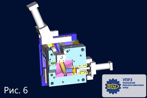
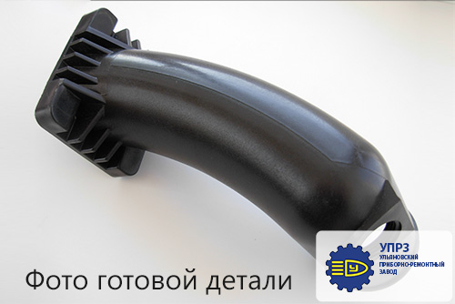
The mold is made, well-adjusted, it works reliably. Details of the new design are successfully applied by the customer (see Fig. 6).
An essential feature of this project is that as a result of solving a complex integrated engineering task by the provider, the customer received a significant economic effect measured in hundreds of percent.
Design-engineer
Romanov S.G.